C#
Aircraft Instrument Control
1
The aim of this
C# project
is to purpose six aircraft cockpit
instruments
usable in forms as any other
C# controls
and to define a generic
instrument class in order to
design any kind of dashboard
instruments.
2
The
controls are
built with bitmaps which are rotated, translated
or scaled before to be displayed. The basic
methods for rotate, translate and scale images
are defined in the mother class. Each control
then uses its dedicated parameters (related to a
physical signification) in order to manipulates
the images.
Aircraft Instruments
- Air speed
indicator: airspeed (kts)
- Attitude
Indicator: pitch (deg), roll (deg)
- Altimeter:
altitude (ft)
- Turn Coordinator:
turn rate (deg/min)
- Vertical speed
indicator: vertical speed (ft/min)
- Heading indicator:
heading (deg)
3
This section explains
in detail the implementation of the basic
functions defined in the
								Instrument
								Control
class.
Rotate Image
Implementation
The rotation of the
image is divided in two main parts:
First, the rotation of the
PaintEventArgs
coordinate system
around the upper left corner of the drawing
area.
Second, the drawing of
the image corrected by translation offset in
order to display the image as if it has turned
around a user defined point.
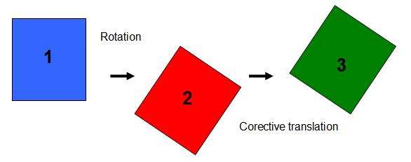
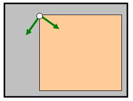
Let’s see step by step:
Step 0:
Initial situation.
Step 1:
Rotate the
PaintEventArgs
coordinate system around
the left upper corner of the paint area.
Corresponding code
sample:
 Collapse | Copy
Code
Collapse | Copy
Code
pe.Graphics.RotateTransform((float)(alpha * 180 / Math.PI));
Step 2:
Draw the image and apply the translation
correction.
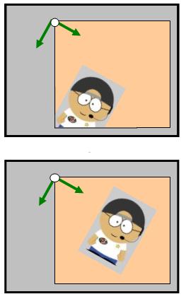
Corresponding code
sample:
Collapse | Copy
Code
pe.Graphics.DrawImage(img, (ptImg.X + deltaX) * scaleFactor, (ptImg.Y + deltaY) *
scaleFactor, img.Width * scaleFactor, img.Height * scaleFactor);
Step 3
(Final step): Put the
PainEventArgs
coordinate system
as found.
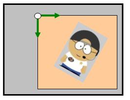
Corresponding code
sample:
Collapse | Copy
Code
pe.Graphics.RotateTransform((float)(-alpha * 180 / Math.PI));
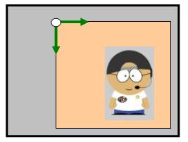
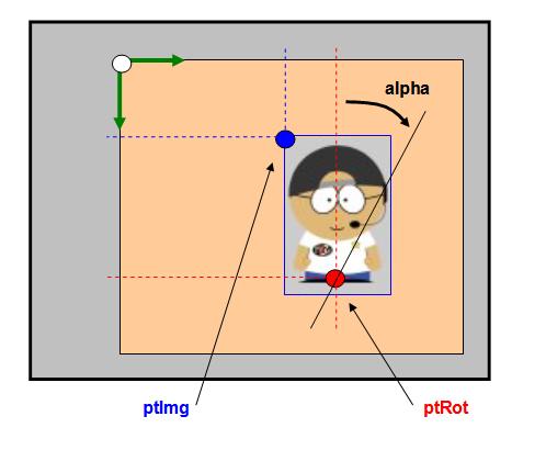
The key point in those
operations is the calculation of the translation
correction coefficients.
The next figure
explains the geometrics considerations:
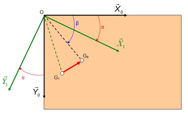
G0 is the
user defined rotation center
G1 is the G0 position
after the step 1.
The aim of this section
is to identify the G1G0
translation and apply the corresponding offset
in order to draw the rotation point as if it has
not moved.
Then we work with the
geometrics definitions:
As a result, the offset
coefficients are:

The corresponding code
sample is as follows:
Collapse | Copy
Code
deltaX = (float)(d * (Math.Cos(alpha - beta) - Math.Cos(alpha)*
Math.Cos(alpha + beta) - Math.Sin(alpha) * Math.Sin(alpha+ beta)));
deltaY = (float)(d * (Math.Sin(beta - alpha) + Math.Sin(alpha)*
Math.Cos(alpha + beta) - Math.Cos(alpha) * Math.Sin(alpha + beta)));
Parameters
- "
pe":
The paint area event where the image will be
displayed
- "
img":
The image to display
- "
alpha":
The angle of rotation in radian
- "
ptImg":
The location of the left upper corner of the
image to display in the paint area in
nominal situation
- "
ptRot":
The location of the rotation point in the
paint area
- "
scaleFactor":
Multiplication factor on the display image
News:
1 UCanCode Advance E-XD++
CAD Drawing and Printing Solution
Source Code Solution for C/C++, .NET V2025 is released!
2
UCanCode Advance E-XD++
HMI & SCADA Source Code Solution for C/C++, .NET
V2025 is released!
3
UCanCode Advance E-XD++ GIS SVG Drawing and Printing Solution
Source Code Solution for C/C++, .NET V2025 is
released!
Contact UCanCode Software
To buy the source code or learn more about with: